Summary
OpenTransport is an open-source, open hardware transport controller for DAW (Digital Audio Workstation) and DVW (Digital Video Workstation) software. It's meant to provide an easy to use and easy to build external transport control surface for those unwilling or unable to spend the incredible costs of a professional control surface.
Design Process
In my career as an audio engineer, I've been hired to work in many professional-grade recording studios and, given the opportunity, I opted to do the necessary editing there due to just how easy editing projects in-studio was. When you have the right equipment, things just go easier.
After college (2014), when I made the decision to forego a more traditional career path and work from home due to family issues, I found editing to be much slower going. I found myself regularly wanting to reach for controls that didn't exist in reality - only on-screen. Physical, tactile controls, I found, make the editing/mixing process so much more seamless; far less conscious thought is required to quickly turn a jog wheel with your pinkie finger than to find the cursor on the screen and drag around the play head. I NEEDED a control surface
After shopping around, I was faced with how prohibitively expensive audio control surfaces like the Mackie Control and Avid's S1 EUCON are (Both $1300). As an audio engineer, while I know how nice it is to mix with a nice, smooth, and shiny control surface, I also know that a control surface doesn't do a single damn thing to improve the sound quality of a mix. I was not going to drop over $1000 on a glorified mouse and keyboard.
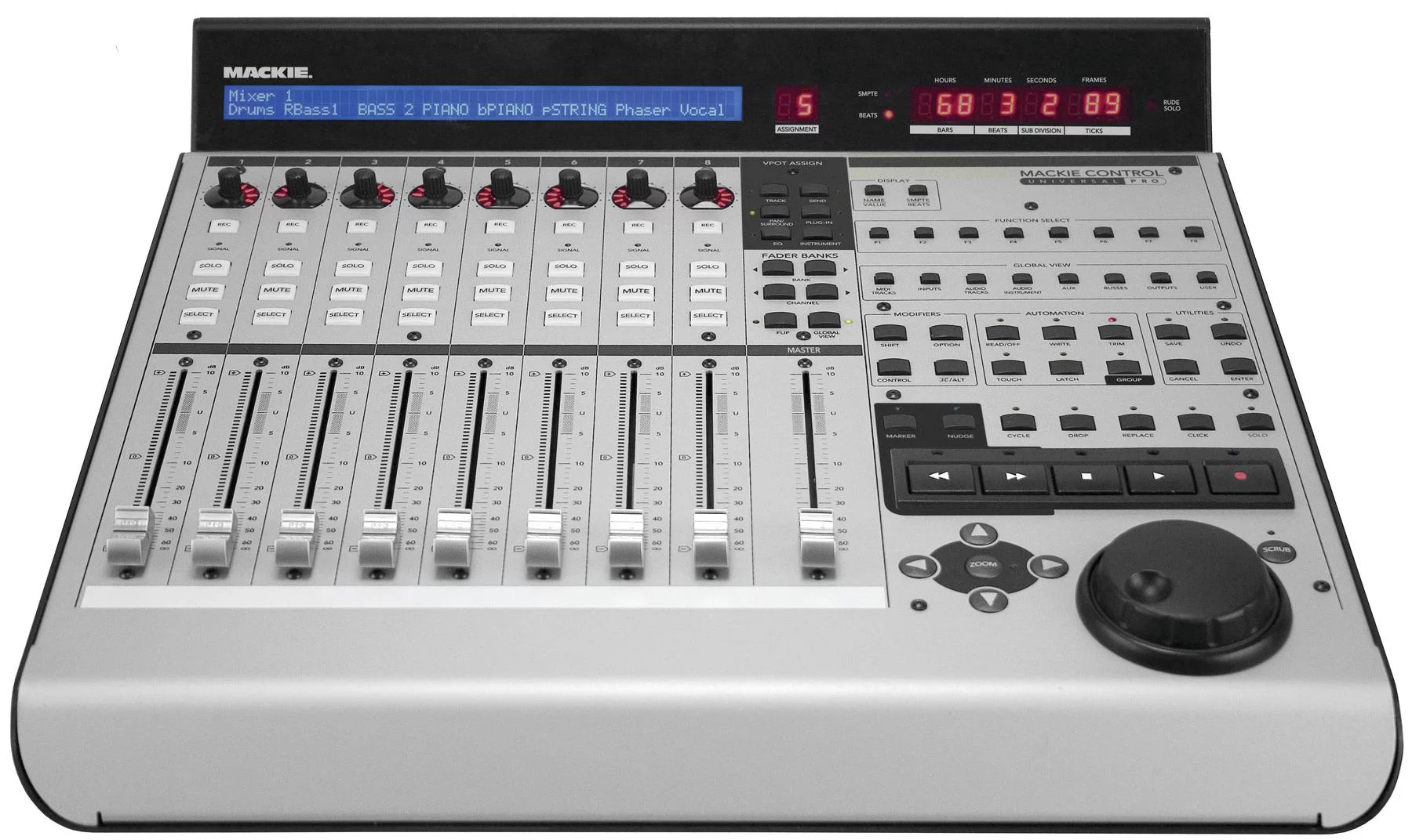
Mackie MCU Pro Control Surface
I was wracking my brain trying to think about how I could solve this problem. And that's, to use the cliche', when it hit me. Arduino microcontrollers can emulate keyboards and mice. I know all the keyboard shortcuts, so why not make one for myself?
This brought on the step that, if not done, has doomed many projects: defining the scope and parameters of the project. So, I sat down and asked myself all of the questions I could think of to help me narrow down what EXACTLY I wanted. How many buttons should I have? How big should it be? Should there be layers of control? Etc...
The very first question that needed answering was about ergonomics. If I was going to be using this regularly, it had to be comfortable. The answer to this, it turns out, was at my local Goodwill.
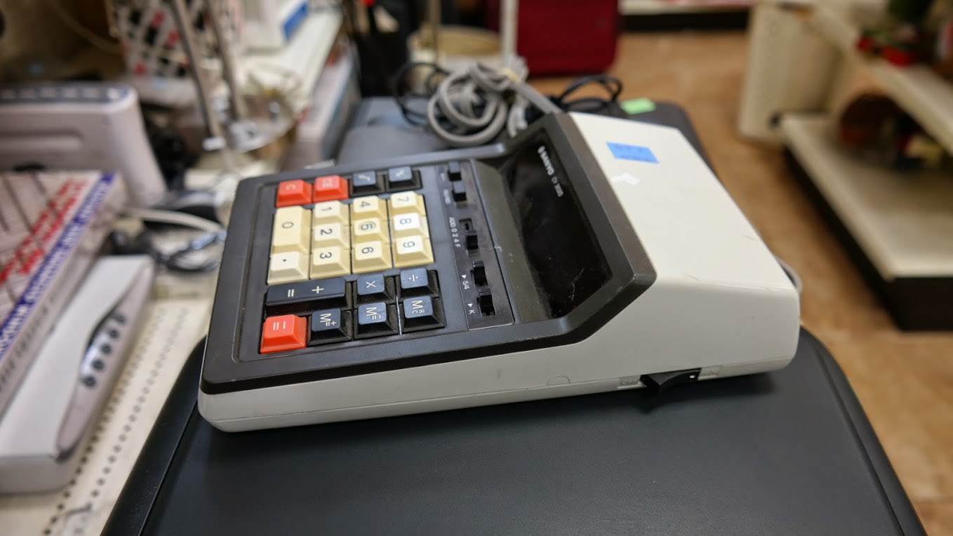
In a case of opting to not to reinvent the wheel, I decided to take a note from the long history of electronic calculators. Desktop calculators have been designed and refined over and over by much smarter people than I, becoming the optimal size and shape for one handed operation. After finding this model at Goodwill, I took some pictures and measurements, and began designing around that basic shape.
One 2AM session at Denny's later and I had my basic layout and design.
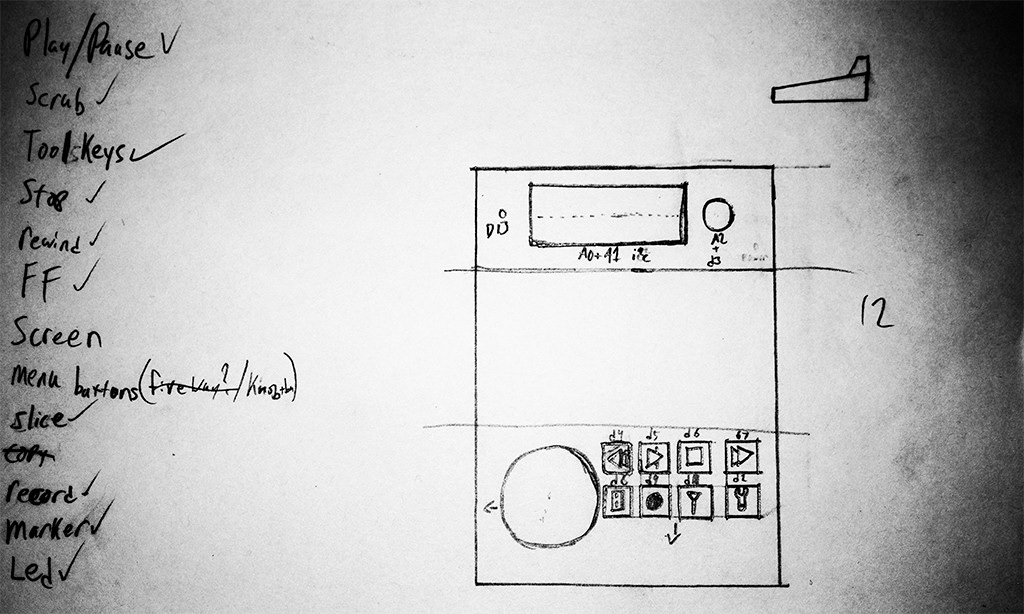
After listing out what functions I would actually need from it, I decided to cut out the middle segment entirely.
I did figure out, though, that I would need a rotary encoder: a thing which I have never used. I mean, I have lots of things with rotary encoders in them, but I've never had one as a part. And, it turns out, it was harder for me to get my hands on one than I thought it would be. Neither RadioShack nor Fry's Electronics had any and, frankly, I didn't want to wait for one to ship to me. Eventually, I found a local electronics parts store that carried them and went for a visit.
I cannot express to you the level of glee I felt when walking into this place. Don't get me wrong, it was a bit of a wreck in there. Messy as all get out, in fact, but it was the right kind of wreck. The same kind of wreck that a fashionista would fawn over if it was filled with nouveaux-retro-chic clothes (or whatever fashion is into these days) instead of oscilloscopes, bulk wiring, and connectors old enough to replace parts for one of the Apollo missions.
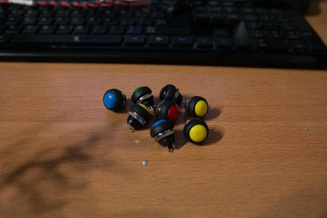
Rotary encoder found and in hand, I set upon their shelves, looking to see if there was anything else I needed and I found the most wonderful little panel mounted buttons ever. They looked like a cross between skittles and personality cores, but in button form, and they have the most satisfying click. In fact, it's less of a "click" and more of a miniaturized "clunk": like those big, red, industrial emergency stop buttons, but smaller.
A few other bits and bobs later and I had all the hardware I needed. Now came time to design the case properly. Taking all of the essential measurements, I began drafting it up in TinkerCAD for 3D Printing. At this point, I was still very new to FDM printing and, though my initial design looked how I wanted, it proved very difficult to print at that time. So, I redesigned it, made some compromises, added some features, and tried again. This time, everything held together during the print (mostly) and (nearly) all of the components fit into their places with (almost) no fuss. It was then that the wiring could begin!

Original design in Tinkercad

Revised design printed in red ABS plastic. Each button labeled with it's corresponding arduino pins

Underside showing wiring
With everything wired up, it was time to start writing the code. This was the most difficult part.
In spite of my original plans, I had decided that it would be "better" to have the controller communicate with the editing software as a MIDI device. This is the method by which professional control surfaces communicate with DAWs. The standard protocol (Mackie HUI) is well established and... barely documented at all. After ages of searching I found a reverse engineered protocol spec sheet but, no matter how hard I tried I simply could NOT get my controller to play nice with my DAW. The connection would break, keys would register to a sniffer app, but not to the DAW, bidirectional control was basically DOA...
Eventually, I gave up on MIDI control and rewrote my original code to emulate a keyboard. This worked 100% perfectly right from the get-go and I am never getting the hours I wasted on MIDI back.
Eventually, I gave up on MIDI control and rewrote my original code to emulate a keyboard. This worked 100% perfectly right from the get-go and I am never getting the hours I wasted on MIDI back.
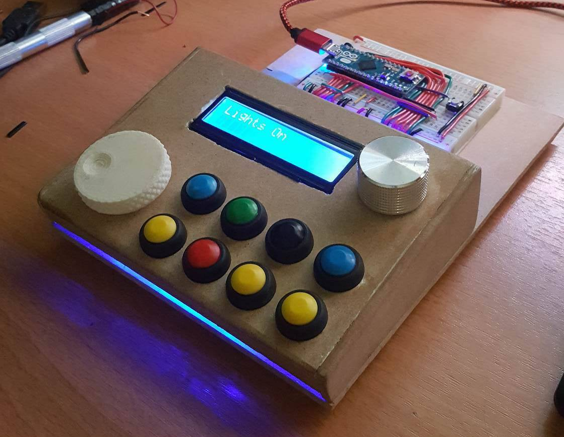
Finally, I decided to rebuild the case for it, but out of MDF as it looked nicer and better fit my aesthetic. I also opted to leave the Arduino on the breadboard with all of the wires exposed because I felt it showed off the DIY nature of it better. I also added an LED to the inside of the case to make it glow. Because it looks cool.